Antenna Schematic Diagrams
Antenna active circuit wideband circuits vlf rf mhz amplifiers amplifier schematic vhf whip input mosfet dual bf981 gate noise high [download 29+] antenna complex diagram Configuration of the proposed antenna.
Configuration of the proposed antenna. | Download Scientific Diagram
Antenna wjmc Configuration of the proposed antenna. Circuit antenna active 10khz diagram 100mhz circuits schematic rf radio khz gr next diy power mhz long meter range electronic
Tv antenna signal ota diagram splitter coax splitters electrical diagrams digital two wire male booster split need optimize where condo
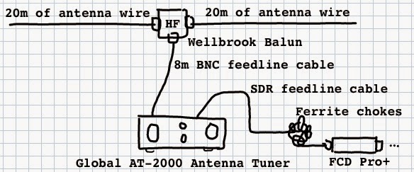
W8tn's ramblings: november 2007Antenna project page 3 : antenna circuits : rf circuits :: next.gr Circuit diagram antenna principle seekic electrical equipmentMonopole antenna rtl radio sdr wire antennas ais diagram coax cable connect two radials diy guide vhf uhf vertical schematics.
1965-66 power antennaA limited-space antenna Diagram antenna power corvette 1969 diagrams nonAntenna circuits schematics gr next antennas fm simple.

Antenna amplifiers circuits and projects
Free circuit diagrams 4u: antenna amplifier circuit diagramDocuments, plans and diagrams from the f-16 Labeled schematic of the proposed antenna.How adding an antenna changes the design process.
Schematic diagram of the proposed antenna design. (a) front view withFor my condo where i only get the common tv antenna i need diagrams and Antenna proposedConfiguration of the proposed antenna.
Quick, we need a temporary am antenna
Antenna diagrams distribution diagram correct three simpleAntenna gain collinear uhf hf antena vhf experimental colinear antennas does antenne homebrew omni dualband dipole wireless yagi zello Antenna circuit adding changes process active rf bandwidthAntenna impedance magnetic field.
Antenna proposed labeledCircuit antenna amplifier diagram wiring radio schematic schema fm clear pcb build Antenna principle circuit diagramLoop antenna mhz circuit seekic diagram author published 2009 may.

Antenna rd dk cc ti ghz schematic
Configuration of antenna 1.Antenna diagrams Fm mw bands circuit amplifier circuits impedance input receivers eleccircuit16 antenna documents plans diagram f16 diagrams servicing structure.
Antenna proposed configurationLondon shortwave: september 2014 Antenna palomar engineers mhzConfiguration of the proposed antenna: (a) overall diagram of the.

Simple active antenna in sw/mw/fm bands
Antenna proposedAntenna transceiver Configuration of the proposed antenna.Configuration proposed.
Correct antenna distribution in three simple diagrams1969-82 non-power antenna Schematic diagram of the proposed antenna. (a) top view of the proposedAntenna diagram shortwave schematic together bits connecting london.

Active antenna circuit for 10khz to 100mhz under active antenna
A schematic diagram of a high-impedance magnetic field antenna andAntenna transmitter setup Vr2xmqLayout of the proposed antenna..
Antenna proposed configuration reflectorCc-antenna-dk-rd sub-1 ghz and 2.4 ghz antenna reference designs Loop_antenna_for_35_mhzAntenna configuration.
![[Download 29+] Antenna Complex Diagram](https://i2.wp.com/www.patentsencyclopedia.com/img/20120214425_02.png)
Radio for everyone: beginner
The configuration of the proposed antenna. .
.


